 |
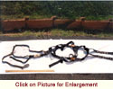
Figure 3 - Photograph showing the as received safety harness and lanyard assembly.
|
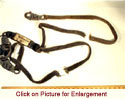 |
Figure 4 - Photograph showing the reconstruction of the two broken lanyards.
|
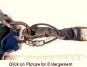 |
Figure 7 - Photograph showing the connection between the safety harness and the energy absorber.
|
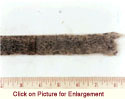 |
Figure 37 - Photograph showing a linear indentation in one side of the second lanyard.
|
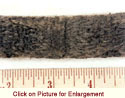 |
Figure 38 - Photograph showing a linear indentation in one side of the second lanyard.
|
 |
Figure 51 - Photograph at 12x showing the second lanyard fracture.
|
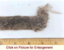 |
Figure 57 - Photograph showing the location of the SEM specimen removal from the second lanyard.
|
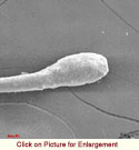 |
Figure 58 - Photograph at 250x showing one of the broken fibers from location no. 1 - second lanyard.
|
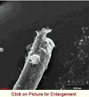 |
Figure 69 - Photograph at 530x showing one of the broken fibers from location no. 2- second lanyard.
|